使用和维护目录AI 442 7201Table of Contents 32Table des Matières 172Contenido 322Table of ContentsUse and care manual3Safety Definitions 43Safety Definitions49 WARNING49 CAUTION4Note:4IMPORTANT SAFETY INSTRUCTIONS5WARNING5General notes5Fire Safety5WARNING5to reduce the risk of a range top grease fire:5a) Never leave surface units unattended at high settings. Boilovers cause smoking and greasy spillovers that may ignite. Heat oils slowly on low or medium settings.5b) Always turn hood ON when cooking at high heat.5c) Clean ventilating fans frequently. Grease should not be allowed to accumulate on fan or filter.5d) Use proper pan size. Always use cookware appropriate for the size of the surface element.5CAUTION5WARNING5TO REDUCE THE RISK OF INJURY TO PERSONS IN THE EVENT OF A RANGE TOP GREASE FIRE, OBSERVE THE FOLLOWING:5WARNING5Risk of fire5WARNING6Risk of fire6WARNING6Risk of fire6WARNING6Risk of fire6WARNING6Risk of fire6WARNING6Risk of fire6Burn Prevention6WARNING6Risk of burns6Child Safety6CAUTION6Cleaning Safety7WARNING7Safe use7WARNING7Risk of injury7WARNING7WARNING7Risk of injury7WARNING7Risk of injury7Proper Installation and Maintenance7CAUTION7CAUTION7WARNING7WARNING8WARNING8Note:8State of California Proposition 65 Warnings8WARNING8Causes of damage9NOTICES:9Protecting the environment9Saving energy9Environmentally-friendly disposal9Operating modes10Air extraction10Note:10Recirculation10Note:10Operating the appliance10Note:10Note:10Operating the appliance10Control panel10Turn on the fan10Note:10Switching on101 Press the # button.102 Press the 1, 2, 3 or Ž button to set the corresponding fan level.10Switching off10Intense level11Switching on111 Press the # button.112 Press the Ž button.11Note:11Switching off11Automatic operation11Switching on111 Push the # button.112 Push the < button.11Switching off11Sensor control11Changing the sensitivity of the sensor111 When the fan is switched off, press the < button and hold it for approx. 4 seconds.112 Press button 1, 2, 3 or the Ž button to change the sensitivity setting.113 Press and hold the < button for approx. 4 seconds.11Saturation notification11Resetting the saturation indicator11Lighting11Switching on or switching off11Setting the brightness11Safety shut-off11Cleaning and maintenance129 WARNING12Risk of burns129 WARNING12Risk of electric shock129 WARNING12Risk of electrical shock129 WARNING12Risk of injury12Cleaning agents12Uninstalling metal grease filter129 WARNING12Risk of injury129 WARNING12Risk of injury121 Open the lock and fold the metal grease filter downwards. For safety reasons, the metal grease filter is locked in place at the rear edge.132 Slightly lift the front edge of the metal grease filter until it can be removed from the holder.13Note:133 Remove the metal mesh filter.134 Pull the two parts of the filter apart, using the recessed grip to help you do this.135 Clean the metal grease filter.136 Clean the appliance from the inside.13Cleaning the metal grease filter139 WARNING13Risk of fire13Notes13In the dishwasher:13Note:13By hand:13Note:13Installing metal grease filter141 Push the two parts of the filter back together. Ensure that the opening on the edge is in the correct place.142 Push the metal mesh filter in completely.143 With the lock facing towards the front, place the metal grease filter in the underside of the appliance and engage the lock.14Note:144 Push the œ button.14Changing the activated charcoal filter (only in circulating-air mode)149 WARNING14Risk of injury14Notes14Method141 Open the lock on both protective grids and inspect the protective grids.142 Remove the old activated charcoal filters.143 Insert the new activated charcoal filters.144 Insert the protective grids.14Troubleshooting159 WARNING15Risk of electric shock159 WARNING15Risk of injury15Fault table15--------15Customer service16To book an engineer visit and product advice16Table des MatièresNotice d’utilisation17Définitions de Sécurité 1817Définitions de Sécurité189 AVERTISSEMENT189 ATTENTION18Remarque :18CONSIGNES DE SÉCURITÉ IMPORTANTES19AVERTISSEMENT19Instructions générales19Sécurité-incendie19AVERTISSEMENT19pour réduire le risque d'incendie de graisse de cuisinière:19a) Ne laissez jamais la surface de cuisson sans surveillance à des températures élevées. Les débordements causent de la fumée et les résidus graisseux peuvent s'enflammer.. Faites chauffer les huiles lentement à feu doux ou moyen.19b) Faites toujours fonctionner la hotte lorsque vous cuisinez à feu vif.19c) Nettoyez les ventilateurs régulièrement. Ne laissez pas la graisse s'accumuler sur le ventilateur ou sur le filtre.19d) Utilisez des casseroles de taille appropriée. Utilisez toujours des récipients adaptés à la taille de la surface de cuisson.19ATTENTION19AVERTISSEMENT19POUR RÉDUIRE LE RISQUE DE LÉSIONS CORPORELLES EN CAS D'UN FEU DE FRITURE SUR UNE CUISINIÈRE, OBSERVER CE QUI SUIT :19AVERTISSEMENT20Risque d'incendie20AVERTISSEMENT20Risque d'incendie20AVERTISSEMENT20Risque d’incendie20AVERTISSEMENT20Risque d'incendie20AVERTISSEMENT20Risque d’incendie20AVERTISSEMENT20Risque d'incendie20Prévention des brûlures20AVERTISSEMENT20Risque de brûlure20Sécurité des enfants20ATTENTION21Consignes en matière de nettoyage21AVERTISSEMENT21Sécurité à l'utilisation21AVERTISSEMENT21Risque de blessure21AVERTISSEMENT21AVERTISSEMENT21Risque de blessure21AVERTISSEMENT21Risque de blessure21Installation et entretien corrects21ATTENTION22ATTENTION22AVERTISSEMENT22AVERTISSEMENT22AVERTISSEMENT22Remarque :22Avertissements de la Proposition 65 de l’État de la Californie22AVERTISSEMENT22Causes des dommages23AVIS:23Protection de l'environnement23Économies d'énergie23Élimination sans nuisances pour l'environnement23Modes de fonctionnement24Mode évacuation24Remarque :24Mode recyclage24Remarque :24Utilisation de l'appareil24Remarque :24Remarque :24Utilisation de l'appareil24Bandeau de commande24Régler le ventilateur24Remarque :24Mise en marche241 Appuyer sur la touche #.242 Appuyer sur la touche 1, 2, 3 ou Ž, pour régler la puissance d'aspiration appropriée.24Arrêt24Vitesse intensive25Mise en marche251 Appuyer sur la touche #.252 Appuyer sur la touche Ž.25Remarque :25Arrêt25Mode Automatique25Mise en marche251 Appuyer sur la touche #.252 Appuyer sur la touche <.25Arrêt25Commande par capteur25Modifier le réglage de la sensibilité du capteur251 Avec le ventilateur éteint, maintenir la touche < enfoncée pendant environ 4 secondes.252 Appuyer sur la touche 1, 2, 3 ou Ž, pour modifier le réglage de la sensibilité.253 Maintenir la touche < appuyée pendant environ 4 secondes.25Indicateur de saturation25Réinitialiser l'indicateur de saturation25Éclairage25Activer ou désactiver25Régler la luminosité25Coupure de sécurité25Nettoyage et entretien269 AVERTISSEMENT26Risque de brûlure269 AVERTISSEMENT26Risque d’électrocution269 AVERTISSEMENT26Risque de choc électrique269 AVERTISSEMENT26Risque de blessure26Produits de nettoyage26Retirer le filtre à graisse métallique279 AVERTISSEMENT27Risque de blessure279 AVERTISSEMENT27Risque de blessure271 Déverrouiller et rabattre le filtre à graisse métallique vers le bas. Pour votre sécurité, le filtre à graisse métallique est encliqueté au bord arrière.272 Soulever légèrement le filtre à graisse métallique au bord avant, jusqu'à ce qu'il puisse être retiré de la fixation.27Remarque :273 Extraire le filtre à tissu métallique.274 Séparer les deux éléments de filtre en les écartant à l'aide des poignées encastrées.275 Nettoyer le filtre à graisse métallique.276 Nettoyer l'intérieur de l'appareil.27Nettoyage du filtre à graisse métallique279 AVERTISSEMENT27Risque d'incendie27Remarques27Au lave-vaisselle :28Remarque :28À la main :28Remarque :28Mettre en place le filtre à graisse métallique281 Rassembler les deux éléments de filtre en les poussant. Veiller à la position correcte de l'ouverture au niveau de l'arête.282 Introduire le filtre à tissu métallique en le poussant jusqu'en butée.283 Mettre en place le filtre à graisse métallique sur le dessous de l'appareil, le verrouillage vers l'avant, et encliqueter le verrouillage.28Remarque :284 Appuyer sur la touche œ.28Changement des filtres à charbon actif (uniquement en cas de mode recyclage)299 AVERTISSEMENT29Risque de blessure29Remarques29Procédez de la manière suivante291 Ouvrez les verrouillages aux deux grilles de protection et enlevez les grilles.292 Enlevez les filtres à charbon actif usagés.293 Mettez en place des filtres à charbon actif neufs.294 Réinsérez les grilles de protection.29Anomalies – que faire ?309 AVERTISSEMENT30Risque de choc électrique309 AVERTISSEMENT30Risque de blessure30Tableau de dépannage30--------30Service après-vente31Demande de réparation et conseils en cas de dysfonctionnement31ContenidoManual de instrucciones32Definiciones de Seguridad 3332Definiciones de Seguridad339 ADVERTENCIA339 ATENCION33Nota:33INSTRUCCIONES DE SEGURIDAD IMPORTANTES34ADVERTENCIA34Indicaciones generales34Seguridad para evitar incendios34ADVERTENCIA34para reducir el riesgo de incendio ocasionado por la grasa en la estufa:34a) Nunca deje las unidades de la superficie sin vigilancia en valores altos. Los derrames por hervor producen humos y salpicaduras grasosas que pueden prenderse fuego. Caliente los aceites despacio a temperaturas bajas o medianas.34b) Siempre encienda la campana al cocinar a una temperatura alta.34c) Limpie los ventiladores extractores con frecuencia. No se debe permitir la acumulación de la grasa en el ventilador ni en el filtro.34d) Use el tamaño de cacerola adecuado. Siempre use utensilios de cocina apropiados para el tamaño del elemento de la superficie.34ATENCION34ADVERTENCIA34PARA REDUCIR EL RIESGO DE LESIONES A PERSONAS EN CASO DE INCENDIO OCASIONADO POR GRASA EN LA ESTUFA, SIGA ESTAS INDICACIONES:34ADVERTENCIA35Peligro de incendio35ADVERTENCIA35Peligro de incendio35ADVERTENCIA35Riesgo de incendio35ADVERTENCIA35Peligro de incendio35ADVERTENCIA35Riesgo de incendio35ADVERTENCIA35Peligro de incendio35Prevención de quemaduras35ADVERTENCIA35Riesgo de quemaduras35Seguridad de los niños35ATENCION36Seguridad en la limpieza36ADVERTENCIA36Seguridad durante su uso36ADVERTENCIA36Riesgo de lesiones36ADVERTENCIA36ADVERTENCIA36Riesgo de lesiones36ADVERTENCIA36Riesgo de lesiones36Instalación y mantenimiento adecuados36ATENCION37ATENCION37ADVERTENCIA37ADVERTENCIA37ADVERTENCIA37Nota:37Advertencias en virtud de la Proposición 65 del estado de California37ADVERTENCIA37Causas para los daños38AVISOS:38Protección del medio ambiente38Ahorro de energía38Evacuación ecológica38Modos de funcionamiento39Funcionamiento con extracción de aire39Nota:39Circulación del aire39Nota:39Operar el equipo39Nota:39Nota:39Operar el equipo39Tablero de control39Ajustar el ventilador39Nota:39Conexión391 Oprimir la tecla #.392 Oprimir las teclas 1, 2, 3 o Ž para ajustar el nivel de ventilador correspondiente.39Desconexión39Nivel intensivo40Conexión401 Oprimir la tecla #.402 Oprimir la tecla Ž.40Nota:40Desconexión40Funcionamiento automático40Conexión401 Oprimir la tecla #.402 Oprimir la tecla <.40Desconexión40Control del sensor40Modificar el ajuste de la sensiblidad del sensor401 Con el ventilador apagado, mantener pulsada la tecla < durante unos 4 segundos.402 Pulsar la tecla 1, 2, 3 o Ž para modificar el ajuste de la sensibilidad.403 Mantener pulsada la tecla < durante aprox. 4 segundos.40Indicador de saturación40Restablecer el indicador de saturación40Iluminación40Conexión/Desconexión del aparato40Ajustar el brillo40Desconexión de seguridad40Limpieza y mantenimiento419 ADVERTENCIA41Peligro de quemaduras419 ADVERTENCIA41Peligro de descarga eléctrica419 ADVERTENCIA41Peligro de descarga eléctrica419 ADVERTENCIA41Peligro de lesiones41Productos de limpieza41Desmontar el filtro de metal antigrasa429 ADVERTENCIA42Riesgo de lesiones429 ADVERTENCIA42Riesgo de lesiones421 Abrir el bloqueo y plegar hacia abajo el filtro de metal antigrasa. Por razones de seguridad, el filtro de metal antigrasa está encajado por el borde trasero.422 Elevar levemente el filtro de metal antigrasa por el borde delantero hasta extraerlo de su soporte.42Nota:423 Extraer el filtro de tejido metálico.424 Separar ambas piezas del filtro con ayuda de las escotaduras de agarre.425 Limpiar el filtro de metal antigrasa.426 Limpiar el aparato desde dentro.42Limpiar los filtros metálicos para grasa429 ADVERTENCIA42Peligro de incendio42Notas42En el lavavajillas:43Nota:43A mano:43Nota:43Montar el filtro de metal antigrasa431 Deslizar y unir ambas piezas del filtro. Asegurarse de que la colocación sea correcta, con la abertura en el borde.432 Insertar el filtro de tejido metálico hasta el tope.433 Colocar el filtro de metal antigrasa en la parte inferior del aparato con el bloqueo hacia delante y enclavar el bloqueo.43Nota:434 Oprimir la tecla œ.43Reemplazar el filtro de carbono activo (solo en funcionamiento con recirculación de aire)449 ADVERTENCIA44Riesgo de lesiones44Notas44Así se procede441 Abrir los dispositivos de bloqueo en ambas rejillas protectoras y quitarlas.442 Retirar los filtros de carbón activo viejos.443 Introducir los filtros de carbón activo nuevos.444 Colocar las rejillas protectoras.44¿Qué hacer en caso de fallas?459 ADVERTENCIA45Peligro de descarga eléctrica459 ADVERTENCIA45Riesgo de lesiones45Tabla de averías45--------45Servicio de atención al cliente46Solicitud de reparación y asesoramiento en caso de averías46文件大小: 1.1 MB页数: 48Languages: English, Français, Español打开用户手册
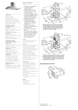
安装指南目录AI 442 7201Table of ContentsInstallation instructions2Safety Definitions29 WARNING29 CAUTION2Note:2IMPORTANT SAFETY INSTRUCTIONS3WARNING3WARNING3WARNING3WARNING3WARNING3Risk of fire3WARNING3Risk of fire3WARNING3WARNING3WARNING4WARNING4Note:4CAUTION4Appliance Handling Safety4WARNING4Risk of injury4Safety Codes and Standards4Electric Safety4WARNING4GROUNDING INSTRUCTIONS4WARNING4WARNING4WARNING5WARNING5TO REDUCE THE RISK OF FIRE, ELECTRIC SHOCK, OR INJURY TO PERSONS, OBSERVE THE FOLLOWING:5WARNING5Risk of electric shock5Related Equipment Safety5State of California Proposition 65 Warnings5WARNING5Installation preparation69 CAUTION6Checking the ceiling6General notes69 WARNING6Risk of death6Exhaust air mode6Note:6Ventilation line6Note:6Electrical connection79 WARNING7Risk of electric shock7Before You Begin7Tools and Parts Needed7Parts Included7All models7Models with circulating-air mode8Ducted operation8Accessory: Remote fan unit8Appliance dimensions9Models with air extraction mode9Models with air recirculation mode9Safety clearances109 WARNING10Risk of fire10Installation10Transport securing device10Fitting the upper support frame101 Before installation, establish the total height of the support frame.10Note:102 Mark the positions of the six screws on the ceiling.10Note:103 Drill the holes and push in the wall plugs so that they are flush with the wall.104 Use four screws to fit the reinforcement plate to the inside of the support frame.105 Use six screws to fasten the upper support frame to the ceiling.10Fitting the lower support frame without using an extension111 Ensure that the lower support frame is in the correct position.11Note:112 Slide the lower support frame into the upper support frame and use 16 screws to secure it at the established total height.11Notes11Fitting the lower support frame using an extension111 Slide each part of the extension over the outside of the upper support frame and use 16 screws to fit them to the upper support frame..112 Ensure that the lower support frame is in the correct position.11Note:113 Slide the lower support frame up into the extension and use 16 screws to secure it at the established total height.124 Fit two reinforcing brackets.12Installing the appliance131 For recirculation mode units only: Fit filters to both sides of the AA 442 810 air recirculation module. Slide the air recirculation module into the support frame from below and hook it in place. Secure it with two screws.132 For combination with internal remote fan unit AR 400 743 only: Unscrew the cover plate from the ventilation hood: Loosen the four screws, remove the cover plate and screw the four screws in again.133 For a combination with external remote fan unit AR4.. only: Use the network cable to connect the external remote fan unit and the ventilation hood’s control module. The plug must snap into place. Connect the mains cable to the control unit.14Note:144 Slide the ventilation hood up into the support frame from below and hook it into the two angle brackets (a).14Note:145 Align the ventilation hood so that it is straight and use seven screws to fasten the ventilation hood to the support frame.14Connect appliance15Notes15Establishing the connection for the exhaust air151 Recirculation mode units with internal remote fan unit AR 400 743: Attach the exhaust air pipe directly to the fan motor's air pipe connector (A).152 Extraction mode units with internal remote fan unit AR 400 743: Attach the exhaust air pipe directly to the fan motor's air pipe connector (A).153 Extraction mode units with external remote fan unit AR 4..:164 Connect it to the air extractor opening (B).165 Seal the joints appropriately.16Connecting the power supply161 Plug the mains plug into the grounded socket.162 If a fixed connection is required, please follow the instructions in the Electrical Connection section.16Attaching flue duct169 WARNING16Risk of injury161 Remove the protective film from the flue ducts.162 Place both parts of the upper flue duct on the appliance such that they fit together.16Model with air extraction mode16Models with air recirculation mode163 Push the upper flue duct up and use two screws to secure it at the top.16Model with air extraction mode17Models with air recirculation mode174 Place both parts of the lower flue duct on the appliance such that they fit together.175 Fit the grease filter.17Additional switching output18Networked operation181 Unscrew the cover plate.182 Press and hold the reset button until both LEDs light up continuously (approx. 5 seconds). Then release the button within 5 seconds.183 Screw on the cover plate.184 After initialization, have a qualified electrician check that the system functions correctly.18Connect Electrical Supply189 WARNING18Risk of electric shock18This appliance is connected with a plug18Removing the appliance191 Remove the grease filter.192 Loosen the flue duct.193 Disconnect the appliance from the power supply.194 Loosen the exhaust air lines.195 Undo the fastening screws.196 Remove the appliance.19Customer service19To book an engineer visit and product advice19Table de MatièresInstructions d’installation20Définitions de Sécurité209 AVERTISSEMENT209 ATTENTION20Remarque :20CONSIGNES DE SÉCURITÉ IMPORTANTES21AVERTISSEMENT21AVERTISSEMENT21AVERTISSEMENT21AVERTISSEMENT21AVERTISSEMENT21Risque d'incendie21AVERTISSEMENT21Risque d’incendie21AVERTISSEMENT21AVERTISSEMENT21AVERTISSEMENT22AVERTISSEMENT22Remarque :22ATTENTION22Sécurité de manipulation de l'appareil22AVERTISSEMENT22Risque de blessure22Codes et normes de sécurité22Sécurité électrique22AVERTISSEMENT22INSTRUCTIONS DE MISE À LA TERRE22AVERTISSEMENT22AVERTISSEMENT23AVERTISSEMENT23AVERTISSEMENT23AFIN DE RÉDUIRE LES RISQUES D’INCENDIE, DE CHOC ÉLECTRIQUE OU DE BLESSURES CORPORELLES, VEUILLEZ SUIVRE LES INSTRUCTIONS SUIVANTES :23AVERTISSEMENT23Risque de choc électrique23Sécurité apparentée concernant l'équipement23Avertissements de la Proposition 65 de l’État de la Californie23AVERTISSEMENT23Préparatifs du montage249 ATTENTION24Vérifier le plafond24Instructions générales249 AVERTISSEMENT24Danger de mort24Mode évacuation24Remarque :24Conduit d'évacuation24Remarque :24Branchement électrique259 AVERTISSEMENT25Risque de choc électrique25Avant de commencer25Outils et pièces nécessaires25Pièces comprises25Tous les modèles25Modèles avec mode recyclage26Modèles avec mode évacuation extérieure26Accessoire : Moteur de ventilateur26Cotes de l'appareil27Modèles avec mode évacuation extérieure27Modèles avec mode recyclage27Distances de sécurité289 AVERTISSEMENT28Risque d’incendie28Installation28Sécurité transport28Montage du châssis-support supérieur281 Avant le montage, définissez la hauteur totale du châssis-support.28Remarque :282 Marquez les positions des 6 vis contre le plafond.28Remarque :283 Percez les trous et enfoncez les chevilles jusqu'au ras de la surface.284 Montez la tôle de renfort par l'intérieur sur le châssis-support à l'aide de 4 vis.285 Fixez le châssis-support supérieur contre le plafond à l'aide de 6 vis.28Montage du châssis-support inférieur sans rallonge291 Veillez à ce que le châssis-support inférieur se trouve dans une position correcte.29Remarque :292 Poussez le châssis-support inférieur dans le châssis-support supérieur et fixez-le à la hauteur totale définie à l'aide de 16 vis.29Remarques29Montage du châssis-support inférieur avec rallonge291 Poussez la rallonge depuis l'extérieur sur le châssis-support supérieur et fixez-la à l'aide de 16 vis.292 Veillez à ce que le châssis-support inférieur se trouve dans une position correcte.29Remarque :293 Poussez le châssis-support inférieur dans la rallonge et fixez-le à la hauteur totale définie à l'aide de 16 vis.304 Montez deux cornières de renfort.30Montage de l'appareil311 En cas de version recyclage uniquement : Mettre en place les filtres des deux côtés dans le module de recyclage de l'air AA 442 810. Introduisez et accrochez le module de recyclage de l’air par en dessous dans le châssis-support. Fixez-le avec...312 Pour la combinaison avec moteur séparé AR 400 743 uniquement : Dévissez la tôle de recouvrement dans la hotte : desserrez 4 vis, retirez la tôle de recouvrement, revissez 4 vis.313 Pour la combinaison avec moteur séparé externe AR4.. : Raccordez le moteur séparé exterrne et le module de commande de la hotte avec le câble secteur. Les fiches doivent s’enclencher. Raccordez le câble secteur au module de commande. Raccor...32Remarque :324 Accrochez la hotte par en bas dans les deux cornières (a) du châssis-support.32Remarque :325 Alignez soigneusement la hotte et fixez-la au châssis-support à l'aide de 7 vis.32Brancher l’appareil32Remarques32Effectuer le raccordement de l'évacuation de l'air331 Appareil du mode recyclage avec moteur séparé interne AR 400 743 : Fixez le conduit d’évacuation directement sur le manchon d’évacuation du moteur séparé(A).332 Appareil de mode d’évacuation avec moteur séparé interne AR 400 743: Fixez le conduit d’évacuation directement sur le manchon d’évacuation du moteur séparé (A).333 Appareil de mode d’évacuation avec moteur externe AR 4.. :334 Effectuez la jonction vers l'orifice d'évacuation d'air (B).335 Étanchez les zones de jonction de façon appropriée.33Effectuer le raccordement électrique331 Brancher la fiche secteur sur la prise avec mise à la terre.332 Si un raccordement fixe est nécessaire, respecter les consignes dans le chapitre Raccordement électrique.33Montage du capot de cheminée349 AVERTISSEMENT34Risque de blessure341 Retirez la pellicule protectrice des capots de cheminée.342 Posez sur l'appareil les deux pièces formant la partie supérieure du capot de cheminée et emboîtez-les ensemble.34Modèles avec mode évacuation extérieure34Modèles avec mode recyclage343 Poussez le capot de cheminée supérieur vers le haut et fixez-le à l'aide de 2 vis.34Modèles avec mode évacuation extérieure34Modèles avec mode recyclage354 Posez sur l'appareil les deux pièces formant la partie inférieure du capot de cheminée et emboîtez- les ensemble.355 Mettez en place le filtre à graisse.35Sortie de commutation supplémentaire35Utilisation en réseau361 Dévisser la tôle de protection.362 Appuyer sur la touche Réinitialiser (Reset) jusqu'à ce que les deux DEL soient allumées en continu (env. 5 secondes). Relâcher ensuite la touche dans les 5 secondes.363 Visser la tôle de protection.364 Faire vérifier le fonctionnement de l'installation par un technicien qualifié après l'initialisation.36Brancher l'alimentation électrique369 AVERTISSEMENT36Risque de choc électrique36Ce apparail est relié avec une fiche36Démontage de l'appareil361 Retirer le filtre à graisse.362 Détacher le capot de cheminée.363 Mettre l'appareil hors tension.364 Détacher les conduits d'évacuation.365 Desserrer les vis de sécurité.366 Enlever l'appareil.36Service après-vente37Demande de réparation et conseils en cas de dysfonctionnement37ContenidoInstrucciones de instalación38Definiciones de Seguridad389 ADVERTENCIA389 ATENCION38Nota:38INSTRUCCIONES DE SEGURIDAD IMPORTANTES39ADVERTENCIA39ADVERTENCIA39ADVERTENCIA39ADVERTENCIA39ADVERTENCIA39Peligro de incendio39ADVERTENCIA40Riesgo de incendio40ADVERTENCIA40ADVERTENCIA40ADVERTENCIA40ADVERTENCIA40Nota:40ATENCION40Seguridad con el manejo del electrodoméstico40ADVERTENCIA40Riesgo de lesiones40Códigos y normas de seguridad41Seguridad con la electricidad41ADVERTENCIA41INSTRUCCIONES PARA LA CONEXIÓN A TIERRA41ADVERTENCIA41ADVERTENCIA41ADVERTENCIA41ADVERTENCIA41PARA REDUCIR EL RIESGO DE INCENDIO, CHOQUE ELÉCTRICO O LESIONES A LAS PERSONAS, OBSERVE LAS SIGUIENTES RECOMENDACIONES:41ADVERTENCIA41Peligro de descarga eléctrica41Seguridad relacionada con los equipos42Advertencias en virtud de la Proposición 65 del estado de California42ADVERTENCIA42Preparativos para el montaje439 ATENCION43Revisar el techo43Información general439 ADVERTENCIA43¡Riesgo de muerte!43Funcionamiento con extracción de aire43Nota:43Conducto de escape43Nota:43Conexión eléctrica449 ADVERTENCIA44Peligro de descarga eléctrica44Antes de empezar44Herramientas y piezas necesarias44Piezas incluidas44Todos los modelos44Modelos con funcionamiento con recirculación de aire45Modelos con evacuación exterior de aire45Accesorios: Motor del ventilador45Dimensiones del equipo46Modelos con evacuación exterior de aire46Modelos con funcionamiento con recirculación de aire46Distancias de seguridad479 ADVERTENCIA47Riesgo de incendio47Instalación47Seguro de transporte47Montaje del bastidor de soporte superior471 Antes del montaje, determinar la altura total del bastidor de soporte.47Nota:472 Dibujar las posiciones para los 6 tornillos en la tapa.47Nota:473 Taladrar los agujeros e introducir los taquetes a presión hasta que queden a ras.474 Montar la lámina de refuerzo con 4 tornillos desde el interior en el bastidor de soporte.475 Sujetar el bastidor de soporte superior con 6 tornillos a la tapa.47Montar el bastidor de soporte inferior sin prolongación481 Cerciorarse de la posición correcta del bastidor de soporte inferior.48Nota:482 Introducir el bastidor de soporte inferior en el bastidor de soporte superior y sujetar a la altura total establecida con 16 tornillos.48Notas48Montaje del bastidor de soporte inferior con la prolongación481 Desplazar la prolongación por el exterior sobre el bastidor de montaje superior y montarlo con 16 tornillos en el bastidor de soporte superior.482 Cerciorarse de la posición correcta del bastidor de soporte inferior.48Nota:483 Introducir el bastidor de soporte inferior en la prolongación y sujetar a la altura total establecida con 16 tornillos.494 Montar dos escuadras de sujeción.49Montaje del aparato501 Solo para versión de recirculación de aire: Colocar el filtro en los dos lados del módulo de recirculación de aire AA 442 810. Introducir y enganchar el módulo de recirculación de aire desde abajo en el bastidor de soporte. Sujetar con 2 torn...502 Solo en combinación con un módulo del ventilador interno AR 400 743: Desatornillar la chapa protectora en la campana extractora: desatornillar los 4 tornillos, retirar la chapa protectora, atornillar de nuevo los 4 tornillos.503 Solo en combinación con el módulo del ventilador externo AR4..: Conectar el módulo del ventilador externo y el módulo de control de la campana extractora con el cable de red. Los enchufes tienen que encajar. Conectar el cable de red al módulo ...51Nota:514 Enganchar la campana extractora desde abajo en las dos escuadras de fijación (a) con el bastidor de soporte.51Nota:515 Enderezar la ampana extractora y sujetarla con 7 tornillos en el bastidor de soporte.51Conectar el aparato a la red eléctrica52Notas52Conexión de la salida de aire521 Aparato de modo circulación de aire con módulo del ventilador interno AR 400 743: Sujetar el tuo de salida de aire directamente en la tubuladura de aire del módulo del ventilador (A).522 Aparato de modo de extracción de aire con módulo del ventilador interno AR 400 743: Sujetar el tuo de salida de aire directamente en la tubuladura de aire del módulo del ventilador (A).523 Aparato de modo de extracción de aire con módulo del ventilador externo AR 4..:534 Establecer la conexión con la abertura de salida de aire (B).535 Sellar convenientemente los puntos de unión.53Montaje de la toma de corriente531 Insertar el enchufe en la toma de corriente con toma a tierra.532 En caso de requerirse una conexión fija, tener en cuenta los consejos y advertencias del capítulo Conexión eléctrica.53Montar los revestimientos de la chimenea539 ADVERTENCIA53Peligro de lesiones531 Retirar la lámina protectora de los revestimientos de la chimenea.532 Colocar las dos partes del revestimiento superior de la chimenea sobre el aparato y acoplarlas.53Modelos con evacuación exterior de aire53Modelos con funcionamiento de recirculación de aire543 Desplazar el revestimiento superior de la chimenea hacia arriba y sujetarlo con 2 tornillos.54Modelos con evacuación exterior de aire54Modelos con funcionamiento con recirculación de aire544 Colocar ambas partes del revestimiento inferior de la chimenea sobre el aparato y acoplarlas.545 Montar el filtro antigrasa.55Salida de conexión adicional55Funcionamiento conectado551 Desatornillar la tapa protectora.552 Pulsar la tecla Reset hasta que los dos LED se iluminen de forma permanente (aprox. 5 segundos). Después de 5 segundos, soltar la tecla.553 Atornillar la tapa protectora.554 Contactar con profesionales calificados para que comprueben el funcionamiento de la instalación tras el reinicio.55Conexión de la alimentación eléctrica559 ADVERTENCIA55Peligro de descarga eléctrica55Este aparato tiene conexión con un enchufe56Desmontaje del aparato561 Retirar el filtro antigrasa.562 Aflojar el revestimiento de la chimenea.563 Desconectar el aparato de la corriente.564 Aflojar las líneas de aire de salida.565 Aflojar los tornillos de seguridad.566 Sacar el aparato.56Servicio de atención al cliente56Solicitud de reparación y asesoramiento en caso de averías56文件大小: 3.0 MB页数: 60Languages: English, Français, Español打开用户手册