Service ManualTable of ContentsSERVICE MANUAL1RM-8/RM-47/RM-481Nokia 7270/Nokia 61701COMPANY CONFIDENTIAL1Amendment Record Sheet2IMPORTANT4Company Policy4Warnings and Cautions5Warnings:5Cautions:5ESD Protection61. General Information22. Parts Lists and Component Layouts23. Service Software and Tuning Instructions24. Service Tools25. Disassembly Instructions26. Troubleshooting Instructions27. System Module28. Schematics2Size: 168 KBPages: 6Language: EnglishOpen manual
Service ManualTable of ContentsGeneral Information1RM-8/RM-47/RM-48 Product Selection2RM-8/RM-47/RM-48 Product and Modules2Accessories List2Technical Specifications2BACK TO MAIN PAGE2Size: 246 KBPages: 12Language: EnglishOpen manual
Service ManualTable of ContentsParts List and Component Layout1Table of Contents2Exploded View of RM-8/RM-47/RM-483Mechanical Parts of RM-84Mechanical Parts of RM-475Mechanical Parts of RM-486Variant Parts7Swap Units8RM-8 parts list9RM-47 parts list32RM-48 parts list53Upper block for RM-8/RM-47 (1DS)85Upper block for RM-48 (1NM)88RM-8 assembly values diagram, bottom92RM-8 assembly values diagram, top93RM-47 assembly values diagram, bottom94RM-47 assembly values diagram, top95RM-48 assembly values diagram, bottom96RM-48 assembly values diagram, top97RM-8/RM-47 upper block assembly values diagram, bottom98RM-8/RM-47 upper block assembly values diagram, top99RM-48 upper block assembly values diagram, bottom100RM-48 upper block assembly value diagram, top101BACK TO MAIN PAGE1Size: 843 KBPages: 101Language: EnglishOpen manual
Service ManualTable of ContentsService Software5Overview5Phoenix5Supported operating systems5Hardware requirements for using Phoenix5Introduction5Installing Phoenix5Uninstalling Phoenix6Data packages7Before installation7Data Package for Phoenix (Product Specific)8Before installation8Installation of Phoenix data package (product specific)9How to uninstall data package13How to Manage Connections13Manual Settings15How to Update Flash Support Files for FPS-8*/FPS- 8C and FLS-4*19Before installation19Installing the flash support files19How to update the FPS-8*/FPS-8C Flash Prommer SW22FPS-8 Activation and Deactivation24Activation24Deactivation26JBV-1 Docking Station SW27Before installation27Installing SW needed for the JBV-1 SW update28Updating the JBV-1 docking station software32RF-tunings: Quick Guide for Tuning With Phoenix35General remarks35Service Tool Concept for RF Tuning Operations36General instructions for tuning:36RF Tuning after repairs37Semi-automatic Calibrations & Measurements - step by step: RX/TX and GSM- Bands38RX tunings38Rx calibration GSM1800 and GSM190040RX band filter response compensation43Rx band filter response GSM85043Autotuning45Rx band filter response GSM 900, GSM 1800 and GSM 190047RX channel select filter calibration47TX power level tuning49Tx power level tuning GSM900, GSM 1800 and GSM 1900 in GMSK mode49Tx power level tuning GSM900, GSM1800 and GSM1900 in EDGE mode53TX I/Q tuning54Fully Automatic Calibration, Tuning & Measurement by Phoenix “Auto-Tune”60Preparations for Phoenix60Compensation of cable and jig losses60GPIB interface60Automatic tuning procedure61Log file61Service Tool Concept For Baseband Tuning Operations63Service concept for RM-8/RM-47/RM-47 baseband tunings and RF testing64Baseband Tuning operations66Energy management tuning66Flashing Setup Instructions69POS (Point of Sales) flash concept69Module jig concept70JBV-1 flash concept71JBV-1 Service concept73Parallel flash concept74BACK TO MAIN PAGE1Size: 2.57 MBPages: 76Language: EnglishOpen manual
Service ManualTable of ContentsView of DKU-5 Cable 24JBV-1 Docking Station and DA-24 Adapter4Product Code4MJ-29 Module Jig6Product Code6RJ-30 Soldering Jig7Product Code7FPS-8 Flash Prommer (Sales Pack)8Sales package code8FPS-8C Parallel Flash Prommer (Sales Pack)9Sales package code9ACF-8 Universal Power Supply10Product Code10SF-26 POS (Point of sales) Flash Adapter11Product Code11FLC-2 DC Cable12Product Code12AXS-4 Service Cable13Product code13XCS-1 Service Cable14Product code14PKD-1 SW Security Device15FLS-4S POS (Point of sales) Flash Device (Sales Pack)16Product Code16PCS-1 Power Cable17Product Code17XRF-1 RF Cable18Product code18DAU-9S MBUS Cable19Product Code19CA-5S Cable20Product Code20XCS-4 Modular Cable21Product code21Printer Cable22Product code22DAU-9T Service Cable23Product code23DKU-5 FBUS/USB Cable24Product code24BACK TO MAIN PAGE1Size: 796 KBPages: 24Language: EnglishOpen manual
Service ManualTable of ContentsDisassembly instructions of lower block3Disassembly instructions of upper block6Domesheet exchange instructions9BACK TO MAIN PAGE1Size: 924 KBPages: 10Language: EnglishOpen manual
Service ManualTable of ContentsSystem Module1Glossary of Terms4Baseband Module Introduction6Features7Environmental Specifications8Normal and extreme voltages8Temperature conditions8Humidity9Vibration9ESD strength9Technical Specifications10UEME10Tiku15Memory16Charging17Battery19Interfaces19Test Points35Main board A side of PWB35Main board B side of PWB35RF Module Introduction36RF Frequency Plan36DC Characteristics37RF Characteristics39RF Block Diagram42BACK TO MAIN PAGE1Size: 783 KBPages: 46Language: EnglishOpen manual
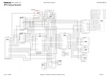
Service ManualTable of ContentsDCT4 Common Baseband1System Connector and USB2UEME, SIM, ZOCUS and Audio3TIKU, SDRAM, Flash and IRDA4FM Radio5Domesheet Keyboard and Vibra6Upper Block7RF Part8Signal Overview9Component Finder10BACK TO MAIN PAGE1Size: 1.13 MBPages: 10Language: EnglishOpen manual